I wrote this little utility to make it easier to get information about Cisco firewalls from Firewall Management center. It doesn’t require a python interpreter so it’s easier for non-programmy types to use. It’s also my first complete thing written in Go and I’m pretty happy about that.
Have a look, and if you have some cool feature ideas let me know in the comments.
ISE Device Extractor is a small python program that extracts all of the Network devices from ISE and outputs them in an Ansible compatible inventory file. Repo is here:
ISE is a good source of truth for network devices. I couldn’t find an existing tool to give me output from ISE that I could use for Ansible playbooks, so I made one. Since YAML is super easy to parse, you can use the inventory file as an input for other tools as well. Example uses would be to check and make sure that devices are categorized correctly, or that the inventory is accurate.
If you would like to test it, devnetsandbox.cisco.com has a reservable ISE sandbox. Search the catalog for ISE and select Identity Services Engine with MUD.
Last week I went down an interesting rabbit hole of MAC address spoofing. I found that while the problem was well defined and easily researched, there were no simple prescriptive recipes for a solution. I thought it might be helpful to share this solution in the hopes it could be useful to others.
I would like to acknowledge the contributions of Marvin Rhoads for technical vetting and proofreading, and Brad Johnson (web page) for climbing down into the rabbit hole with me and lending his considerable expertise.
Media Access Control (MAC) Addresses commonly are used to identify endpoints for purposes of access control and authorization on access layer networks that have yet to implement 802.1x (dot1x) device authentication. The problem with this approach is MAC address spoofing is trivial to implement. However, with a defense in depth approach using basic tools and techniques, the risk and impact can be largely mitigated.
To explore the issues, we are going to evaluate the case of an organization that had recently implemented a network access control solution. A network penetration tester easily bypassed their access controls by cloning a mac address from an IP phone to a Linux laptop computer,
Background
The organization had recently implemented Cisco Systems Identity Services Engine (ISE) and had hired a pen-testing firm to evaluate its efficacy in preventing unwanted access to the network. In general, Network Access Control (NAC) implementations take a phased approach to control risk and get immediate value from the tool, and this was the case here.
At the time the penetration test was performed, some of the network was using 802.1x authentication with digital certificates, and some of the network was using MAC Authentication Bypass (MAB) combined with device profiling to determine the correct level of authorization for a connecting device.
Additionally, the Authorization policies weren’t fully implemented, so effectively authorization was a simple ‘yes/no’ result where full access is granted based on a device profile match.
When the Pentester did her work, she grabbed the MAC address off the back of an IP phone in a common area, applied it to her Linux laptop computer, and used the network cable from the IP phone to connect to the network. ISE recognized her computer as the IP phone, and she was granted unrestricted access to the network.
The information security team had the impression that ISE was able to handle a basic access layer attack like MAC address spoofing, and wanted some answers regarding how this happened and what could be done to mitigate it until they were able to roll out dot1x authentication
Analysis
Before getting into the details, we will set the stage by briefly reviewing how the ISE profiler works. Then we will:
Dive into what happens when Windows and Ubuntu Linux devices connect to the network with the same MAC address as a test IP phone
Review the ISE Anomalous Endpoint Detection (AED) feature and explain why it is ineffective in this case
ISE profiler primer
The ISE profiler has 11 modules that ingest information from a variety of sources to build a database of endpoints and endpoint attributes. The primary key for this data structure is the MAC address of the endpoint. The ISE user interface provides an interface to view the endpoint database and inspect individual endpoints through the Context VisibilityEndpoints Menu.
Endpoint Database and Endpoint Attributes
Figure – endpoint database
By clicking on the MAC address of the endpoint, we can view detailed information from the database
Figure – Summary information about the endpoint
In figure 2, we can conclude that Media Access Control (MAC) Authentication bypass is being employed because the username is the same value as the MAC address. Ultimately this means we are not doing authentication. However, we can use the profiling information to authorize a specific level of access, which we will review later.
In the following image, we can see some attributes that ISE learned, as well as a value called Total Certainty Factor (TCF)
Figure TCF and attributes learned from Device Sensor
So how is this information employed? ISE evaluates the attributes against a set of profiling policies, the policy with the highest TCF is assigned as the endpoint policy for that device. We then use that endpoint policy to decide how much access (if any) to authorize.
ISE profiling policies
Profiler polices assign point values to matching attributes. The highest Total Certainty Factor (TCF) score wins. The policies are arranged in a tree-like structure from coarse to finer-grained. The minimum score at each level of the tree has to be met before the child nodes will be evaluated.
Figure – Profiler policy for a 7965 IP phone
Logical polices
Logical policies are used to group like devices together where a collective policy decision would be made for them. It is the functional equivalent of putting users into groups for granting access to files and folders on a computer.
Figure – Logical profile
Policy Set Authorization (AuthZ) rule
Finally, we use the logical profile in an authorization rule, which then directs the network device to apply the authorization we have defined.
Figure – Authorization rule for IP Phones
So how does mac address spoofing bypass this system? Now that we have set the stage, we can start to talk about that.
Effect of MAC address spoofing on the profiler
Now we will see what happens when we try a Windows and then a Linux Computer using the MAC address of our previously profiled phone
Windows laptop
For our first, we will connect a Windows 10 computer to the switch, with the same mac address as the test phone, and we will see what changes.
Figure – Windows 10 laptop
Reviewing figure 7, There are 4 items highlighted:
Authorization profile
Total Certainty Factor
Dhcp-class-identifier
Host-name
The reason why we have an authorization result of DenyIP is that I had configured Anomalous endpoint detection. The dhcp-class-identifier change triggered the Anomalous Endpoint flag on the endpoint to true. I then used this as a condition in a rule to return the DenyIp authorization result. We will dive into the details in the AED section.
There are two main takeaways here:
ISE was able to respond to the MAC address spoofing attempt and flagged the endpoint.
The attributes from when the phone was profiled are still present, even though we can be reasonably sure the laptop did not send them.
It is the second point that’s important to understand. The absence of a value being sent (that was sent prior) does not equal a change as far as the profiler is concerned. The TCF changed by -30 because the dhcp-class-identifier value is scored in two locations for 10 and 20 points, respectively.
Figure – how attribute matches are scored
It is essential to grasp that except for DHCP, when endpoint attributes accumulate, they remain until there is a change. Usually, this is not too much of a problem….
Once a device has had the AED flag set, the only way to clear the condition is to delete the endpoint. I am going to unplug the laptop, delete the endpoint, and next, we will try the Ubuntu Laptop.
Linux laptop
The endpoint was deleted, the phone plugged back in, and our endpoint has been recreated with the phone accurately identified. Now let us plug in the Linux laptop and take a look.
Figure – Linux laptop
The only informational DHCP attribute Ubuntu sends in its DHCP discovery request is host-name. The result is that the laptop received the IP_phones Authorization Profile. Why didn’t AED fire and block the endpoint?
Because we are not getting anything actionable, there is nothing to trigger ISE. If the residual attributes left from when the phone was plugged in were not persistent, this would trigger a reprofile and we would be able to do something. The reasons the attributes are cached are understandable, but it presents a difficulty here.
The main takeaways here are:
In default DHCP configuration, the Ubuntu laptop doesn’t give up any useful information.
We just got p0wned.
Anomalous Endpoint Detection (AED)
We saw that AED worked in the case of a Windows machine but not in the case of the Ubuntu Linux machine. Let us take a closer look at AED and see how it works.
According to the Documentation (Cisco, 2018), AED can trigger on a change in one of three things.
NAS-Port-Type (i.e. wired or wireless)
DHCP-class-identifier
Endpoint policy change
If any of these conditions occur with AED enabled, the endpoint will be flagged. It should be noted that not getting the class-id when it was received prior will not trigger AED. And this is why we got p0wned by Linux.
While we are here, let us walk through how to configure AED.
Enable it
Create an Authorization exception rule that matches on the AnomalousBehaviour endpoint flag
Apply an authorization profile that allows the device to receive an address (optional, I’ll explain)
Enabling AED
In the profiler configuration settings, check off the AED boxes.
Figure – Enable AED
Define a DACL that only allows DHCP/Bootp
Reference the DACL in an authorization profile:
In the policy set, create an Exception rule that conditions on AnomalousBehaviour Endpoint Attribute. In this case, I also conditioned on IP phones because I only want the scope to cover the specific assets of interest. Assign the AuthZ profile.
Why the access-accept, and why give out an IP address? The simple answer is visibility. If we give the device an IP address, ISE can ingest the DHCP attributes and we will be able to tell from the ISE UI that a different device has been plugged in even though the endpoint was flagged by AED. If we were to prevent all access, we might not receive any new information until the endpoint was deleted and recreated.
Proposed Solution
Now we have discussed the limitations of AED and the inability to act with the Linux laptop because ISE is not receiving any actionable information. Even if we rolled out 802.1x, there might still be devices that require using MAB, so we cannot sidestep the issue.
There is a straightforward solution: Implement first-hop security and require the client to send a class-identifier in its DHCP requests. If the class-identifier does not match, or there is not one sent, then the device will not obtain an IP Address.
There are three tools we will employ to accomplish this:
DHCP Snooping (which you have already enabled on your network, right?)
IP source guard (depends on DHCP snooping, prevents user-assigned static addresses)
DHCP policy on the DCHP Server
DHCP Snooping
DHCP snooping listens to DHCP traffic and creates a table of IP MAC and Interface bindings. Configuring DHCP snooping is very straightforward. However, consult the documentation and make to understand how to scope it to specific VLANS and trust the uplinks leading towards the DHCP server. (Cisco Security Configuration Guide, no.date.)
Sample configuration:
ip dhcp snooping vlan 10,100
no ip dhcp snooping information option
ip dhcp snooping
!
interface GigabitEthernet1/0/48
!
!———–Trust the northbound link towards the DHCP server
ip dhcp snooping trust
!
Binding example:
IP Source Guard
IP source guard will check the DHCP snooping binding table as well as the static binding table for a matching entry when IP packets are received on the switchport. If there no match, the traffic will be dropped. This prevents an attacker from statically applying an IP address.
Ip source guard is a one-line command:
interface GigabitEthernet1/0/36
!
ip verify source
Verification output:
DHCP Policy
To close the loop, we will create a DHCP policy that will only offer addresses to devices that send the correct class-id in the DHCP Discover or Request packets. (Microsoft Docs, 2016). Creating the policy consists of the following steps:
Create a vendor Class
Create a policy that references the vendor class
Creating the Vendor Class.
In the DHCP management tool, right-click on the IP Address family icon and select define vendor classes. When defining the class, the beginning or the end of the string can be used for wildcard matches, but the characters must be exact. An easy way to get this is to copy it from the endpoint attribute in ISE.
Creating the policy that references the vendor class
In the policies folder, right-click and select new policy. This will launch the new policy wizard.
On the configure conditions window, click add to add a condition.
Select vendor class, operator, the vendor class defined earlier, then wildcard if desired. Select add, and click ok.
Use all of the addresses in the scope. NOTE: once done, the policy will reserve 100% of the addresses even if disabled. The policy must be deleted to release the reservation.
Click through the rest of the wizard and select finish.
Conclusion
Strong authentication using 802.1x will protect against identity spoofing, but it is a significant undertaking for existing networks, and it takes time to roll out. Additionally, there may be devices that cannot perform 802.1x authentication, but they require network access. Therefore, we have to deploy a defense-in-depth strategy to secure the access network when device authentication is not possible.
Recommendations
Use 802.1x with certificate authentication whenever possible.
If you have a NAC such as ISE, employ least privilege authorization to mitigate impact.
Deploy First Hop Security (FHS), primarily DHCP snooping and IP Source Guard.
DHCP servers are a good control point to perform policy enforcement. Take advantage.
Take operations security practices seriously and follow the cycle.
In PKIFNE part 10 (link), I introduced Cisco IOS Certification Authority, reviewing its use cases, deployment options, and enrollment challenges. In this installment we’re going to dip our toes in the water and put together a basic working configuration utilizing Simple Certificate Enrollment Protocol (SCEP). This design is suitable for production deployment in a small to medium sized network.
Notes:
There are some interactive steps in turning up a CA and enrolling spokes. Also there is a one line configuration difference between a spoke and a hub. for these reasons, the configurations are broken up into several snippets. After the snippets I’ll show you what the output should approximately look like, and we’ll follow that up with some verification commands for testing and troubleshooting your deployment.
In this example, we’re going to do a spoke and hub network, with a CA sitting behind the hub. For simplicity’s sake, I’ll forgo some of the things I would normally include in this kind of design (such as DMVPN with FVRF) so we can focus on the PKI part. Just know that this design is intended to work with a spoke and hub vpn topology.
Demonstration Topology
Quick verification that our toplogy is functional and we have the routes:
Verification from r5
Root CA
Overview
In this simple design we have a single root issuing CA. Let’s go ahead and pop in a somewhat minimal working config. We’re going to:
Generate a 2048 bit RSA keypair called CA
create a folder to hold our pki database
Create a CA server called CA
set the database level to name
set lifetimes on our CA and client certificates (feel free to alter as needed)
set the issuing CA information
Automatically grant certificates
enable the ios HTTP server
Disable all HTTP modules except for the SCEP server
Put an access control list on the HTTP server
CA configuration snippet 1
!------Basic IOS CA-----------!
Crypto key generate rsa modulus 2048 label CA
!
!**** leave blank line after pki*****
do mkdir pki
pki

!
!
ip http server
!
!*****Whitelist for SCEP clients*****
access-list 99 permit 10.1.1.1
access-list 99 permit 10.1.1.2
access-list 99 permit 10.1.1.3
access-list 99 permit 10.1.1.4
access-list 99 permit 10.1.1.5
!
ip http access-class 99
!
crypto pki server CA
Database url flash:/pki/
Database level names
Lifetime ca-certificate 7000
Lifetime certificate 3500
issuer-name cn=r1.densemode.com,O=Densemode,OU=IT
!
!***Grant auto should be combined with http acl to restrict access***
grant auto
!
!*****you will need to interactively enter a passphrase****
!*****After no shut command is issued*****
no shut
This approximately what you should expect to see when turning up the CA:
CA configuration Snippet 2
!——————Disable unused http session modules—————!
ip http secure-active-session-modules none
ip http session-module-list RA SCEP
ip http active-session-modules RA
Client configuration
Overview
The basic workflow is pretty straightforward.
Configure a trust point
Authenticate the CA
Enroll the device with the CA
These are the features we’re going to configure on the client:
!----—router enrollment config-----------!
!*****This goes on the client routers in your topology*******!
!*****Be sure to change the subject-name and fqdn fields*****!
!*****To match your devices*******
!*****Ansible+jinja2 templates would be a great way******
!*****To template this configuration**********
!
Crypto key generate rsa modulus 2048 label CA
!
crypto pki trustpoint CA
Enrollment url http://10.1.1.1
source interface lo0
subject-name cn=r2.densemode.com,O=Densemode,OU=IT
Fqdn r2.densemode.com
Rsakeypair CA
!
!******Accept the CA certificate*****
Crypto pki authenticate CA
you’ll get a prompt asking you to verify you trust the fingerprint of the CA certificate:
Client configuration snippet 2
!******Follow the onscreen prompts****
Crypto pki enroll CA
There will be a short series of prompts prior to the enrollment request being sent to the CA. If everything is in order you get a success notification a few seconds after the request is sent out.
Client configuration snippet 3
!***** Use this on remote spokes to solve CA chicken and egg *****
!***** Reachability problem *****
!***** It's not a security risk because the hub router *****
!***** Will perform the validity checks *******
!
crypto pki trustpoint CA
revocation-check none
Verification of CA
Verification commands:
show crypto pki server
show crypto pki certificates verbose
show ip http server session-module
show ip http server status
show access-list
Our Certification Authority is up and running
Using the ‘show pki server‘ command We can see here that our CA is up and running, along with operational and configuration information.
CA Certificate
The ‘show crypto pki certificates verbose‘ command allows us to inspect the CA server certificate. Notice the certificate usage is signature. This certificate will be used to digitally sign all certificates issued by the CA
http server module status
‘show ip http server session-module‘ can be used to verify we’re only running the minimum services needed for the CA to act as a SCEP server to issue certificates in-band over the network
show ip http server status
This truncated output ‘show ip http server status’ Allows us to verify the access list devices that are allowed to communicate with the SCEP server. In this case it’s access list 99.
http access list example
As we can see here, our access list allows only the loopback interfaces of our routers to request certificates from the CA. For a production network this is vital if you’re going to configure the CA to automatically grant certificates.
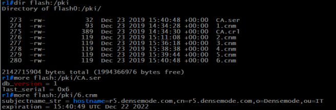
Exploring the contents of the CA database
contents of the pki database
In our sample configuration, we placed the CA database under a folder called PKI. As you can see from the output, there is a:
Serial number file
Certificate Revocation List (CRL)
A file for each certificate issued with the serial # as the filename.
Since we did a database level of name, the serial number file contains the hostname and expiration date of the issued certificate. If you needed to revoke a certificate for a device, this is how you would verify you’re revoking the correct certificate. It’s also why we set the database level to name. 🙂
Client Verification
show crypto pki trustpoint status
show crypto pki certificates verbose
show run | section crypto pki trustpoint
Verifying trustpoint status
The command ‘show crypto pki trustpoint status’ allows to verify that the Trustpoint is properly configured and we have a certificate issued from the CA. We can also inspect the fingerprint of the CA certificate and the router certificate.
Viewing a router certificate in verbose mode
‘Show crypto pki certificates verbose’ allows us to inspect our router certificate in detail. This is an easy way to check the validity period of your certificate and verify that you used a suitably strong keypair in your certificate request.
Trustpoint configuration
‘show run | s crypto pki trustpoint‘ Enables us to check a couple of important details the other commands can’t give us. The important ones among these are:
source interface
revocation-check
Source Interface
Because we’re setting an Access Control List (ACL) on the web server of our issuing CA, it’s important to source the packets from the IP Address that’s in that access list. If we don’t explicitly set the interface, the router will use the routing table to decide which ip address to use.
Revocation Check
In many common designs, the router will not have reachability to the CA until its vpn tunnels come up. However if certificate authentication is being used to form the tunnel, by default the router will attempt to use SCEP to request the Certificate Revocation list (CRL), and the revocation check will fail. We have a chicken and egg problem
Certificate Auth VPN and revocation checks
The solution is straightforward. Since all spokes must transit the hub router to reach the CA, we can have the hub router perform revocation checks and disable it on the spokes. In this way, you can revoke a certificate for a spoke and will be effective as the hub will no longer accept connections from it, preventing the revoked device from coming up on the network.
When we’re inspecting a spoke, we want to see ‘revocation-check none’ in the configuration output.
Revoking a certificate
One of the useful features of IOS CA and PKI in general is we can revoke a certificate at will. For VPN applications this is much better than pre shared keys. In the following exmample, let’s imagine that R5 is being decommissioned.
Checking the serial # on the router
using ‘show crypto pki cerfificate’ on router 5, we can see that the serial number of the certificate is 7. Let’s verify this on the CA.
Verifying the serial # on the CA
using the more command, we can view the contents of certificate serial #7 in the CA database.
Let’s go ahead and revoke the certificate
Revoking a certificate
we revoked the certificate using cry pki server <ca name> revoke <serial #>. This will cause the crl file to be updated so enrolled devices with revocation checking will stop accepting the certificate.
Wrap up
There you have it, a basic utilitarian IOS CA configuration. There are a lot of details left out such as auto-renewal, whether or not to make the private key of the CA exportable for DR purposes, etc. But this is a good 80% solution in my opinion.
Hope you found this useful and I’ll see you around.
In the next few PKI for network engineers posts, I’m going to cover Cisco IOS CA. If you’re studying for the CCIE security lab or you’re operating a DMVPN or FlexVPN network, and you’d like to use Digital certificates for authentication, then this series could be very useful for you.
Introduction
IOS-CA is the Certification Authority that is built into Cisco IOS. While not a full featured enterprise PKI, for the purposes of issuing certificates to routers and firewalls for authenticating VPN connections it’s a fine solution. It’s very easy to configure and supports a variety of deployment options.
Key points
Comes with Cisco IOS
Supports enrollment over SCEP (Simple Certificate Enrollment Protocol)
RSA based certificates only
Easy to configure
Network team maintains control over the CA
Solution can scale from tiny to very large networks
Deployment Options
IOS-CA has the flexibility to support a wide variety of designs and requirements. The main factors to consider are the size of the network, what kind of transport is involved, how the network is dispersed geographically, and the security needs of the organization. Let’s briefly touch on a few common scenarios to explore the options.
Single issuing Root CA
For a smaller network with a single datacenter or a active/passive datacenter design, a single issuing root may make the most sense. It’s the most basic configuration and it’s easy to administer.
This solution would be appropriate when the sole purpose of the CA is to issue certificates for the purpose of authenticating VPN tunnels for a smaller network of approximately a hundred routers or less. Depending on the precautions taken and the amount of instrumentation on the network, the blast radius of this CA compromise would be relatively small and you could spin up a new CA an enroll the routers to it fairly quickly.
The primary consideration for this option is CA placement. A good choice would be a virtual machine on a protected network with access control lists limiting who can attempt to enroll. The CA is relatively safe from being probed and scanned, and it’s easily backed up.
Fig 1. Single issuing root
Offline Root plus Issuing Subordinate CAs
For a network that has multiple datacenters and/or across multiple continents it would make more sense to create a Root CA, then place a subordinate Issuing CA each datacenter that contains VPN hubs. By Default IOS trusts a subordinate CA, meaning the root CA’s certificate and CRL need not be made available to the endpoints to prevent chaining failure.
As in the case with any online/Issuing CA, steps should be taken to use access controls to limit access to HTTP/SCEP
Fig 2. Offline Root
Issuing Root with Registration Authority
Fig 3. Single root with Registration authority
In this design, there is still a single issuing root, however the enrollment requests are handled by an RA (Registration Authority). An RA acts as a proxy between the CA and the endpoint. This allows for the CA to have strict access controls yet still be able to process enrollment requests and CRL downloads.
Offline Root & Issuing Subordinate CAs w/RA
The final variation is a multi-level PKI that uses the RA to process enrollment and CRL downloads. This design provides the best combination of security, scaling, and flexibility, but it is also the most complex.
Bootstrapping remote routers
Consider a situation where you’re turning up a remote router and you need to bring up your transport tunnel to the Datacenter. The Certification authority lives in the Datacenter on a limited access network behind a firewall. In order for the remote router to enroll in-band using SCEP, it would need a VPN connection. But our VPN uses digital certificates.
There are three options for solving this:
Sideband tunnel w/pre-shared key
This method involves setting up a separate VPN tunnel that uses a pre-shared key in order to provide connectivity for enrollment. This could be a temporary tunnel that’s removed when enrollment is complete, or it could be shut down and left in place for use at a later time for other management tasks.
A sideband tunnel for performing management tasks that may bring down the production tunnel(s) is useful, making this a good option. It’s main drawback is the amount of configuration work required on the remote router. It also depends on some expertise on the part of the installer, a shortcoming shared with the manual enrollment method.
Registration Authority
A Registration Authority is a proxy that relays requests between the Certification Authority and the device requesting enrollment. In this method an RA is enabled on the untrusted network for long enough to process the enrollment request. Once the remote router has been enrolled the the transport tunnels will come up and bootstrapping is complete.
Using a proxy allows in-band enrollment with a minimum amount of configuration on the remote router, making it less burdensome for the on-site field technician. The tradeoff is we’re shifting some of that work to the head end. Because the hub site staff is likely to possess more expertise, this is an attractive trade-off.
Manual/Terminal enrollment
In this method, the endpoint produces a Enrollment request on the terminal formatted as base64 PEM (Privacy Encrypted Mail) Blob. The text is copied and pasted into the terminal of the CA. The CA processes the request and outputs the certificate as a PEM file, which is then pasted into the terminal of the Client router.
While this does have the advantage of not requiring network connectivity between the CA and the enrolling router, it does have a couple of drawbacks. Besides being labor intensive and not straightforward for a field technician to work with, endpoints enrolled with the terminal method cannot use the auto-rollover feature, which allows the routers to renew certificates automatically prior to expiration. The author regards this is an option of last resort.
CRL download on spokes problem
The issue here is when the spoke router needs to download the certificate revocation list (CRL) but the CA that has the CRL is reachable only over a VPN tunnel, that cannot come up because the spoke can’t talk to the CA to download a unexpired copy of the CRL in order to validate the certificate of the head end router.
This is actually a pretty easy problem to solve. Disable CRL checking on the spoke routers, but leave it enabled on the hub routers. This way the administrator can revoke a router certificate and that router will not be allowed to join the network because the hub router will see that it’s certificate has been revoked.
Wrap-up
Ok, so there are the basics. In the next installment, we’ll step through a minimum working configuration.
I sat my second attempt at the CCIE security lab on Monday, March 5th, 2018. This time I got the pass. It was not without a bit of drama.
TL;DR: It’s a very tough exam, harder than you think, harder than you remember. Fight with everything you have until the proctor tells you to stop.
The longer version.
Had the usual anxiety thing in the days leading up to lab day. Did what I could to minimize it. Got ok sleep the night before. On Lab day I wasn’t nearly as nervous as I was in January.
Tshoot. I came out swinging and quickly solved most of the tickets. Then I had an issue with ISE that left me dead in the water for half an hour. left one ticket unsolved.
Diag was like last time, pretty easy, chance to take a breather and get ready for the main event.
Config started out well, was flying through the first few tasks. Had some annoying issues related to code and platform differences between my personal lab and the actual exam, don’t recall that happening the last attempt.
Then the trouble began.
ISE was acting up, so I attempted to restart it. Application shut down dirty with database errors and would not start. While all this was going on I was trying to work on other stuff and keep moving. Eventually the proctor got ISE running somehow, but the database corruption was an issue and ISE wasn’t adding endpoints to the database, which made several tasks impossible to complete. The lowest point was when he was sending people home, and I knew I didn’t have the points. When he said I could continue I put my head down and kept grinding.
I was just about out on my feet but I kept battling. When I was told I’d have to stop, I looked at my scorecard to add the points, and all the tasks that could be completed were. Scorecard said I had the points with a small cushion. Would the tasks verify though?
To my amazement I got the email about 3 hours later with the good news.
Much respect to the proctor who probably stayed at work late in order to let me make up the time lost by the ISE debacle. Those folks have a very tough job putting up with us.
Final thought: The CCIE lab is **always** so much harder than you remember it. You can’t simulate what it’s really like. Even after just 7 weeks gap I was going “what the hell!?!”.
Now I get to make things up to my wife and try to lose the 10 lbs of body fat I put on in the final push.
This is a lab topology I put together in EVE-NG to help me sharpen up my knowledge and skills with IKev2/FlexVPN. The baseline configuration uses pre-shared keys and there’s quite a bit of preconfigure.
Screenshot of topology
Here’s a screenshot of the topology. I’ll give a big shout out to whomever can explain why tunnel 100 between r1 and r2 exists. 🙂
Description
There’s two initial versions in the repo.
There’s the actual challenge lab where I removed some bits of config here and there to make it more fun.
There’s a partially completed version using pre-share keys. flex mesh works, the ASA part works, flex client works. No config on R7. You could use this as a starting point to work on the tasks in the lab.
Fire it up and let me know what you think! If you get everything working, feel free to do a pull, inject some faults and create some troubleshooting labs. Here’s the link to the github repo:
In this installment of PKI for network engineers, we’re going to install an online responder. the Online responder implements a lightweight version of OCSP or Online Certificate Status Protocol. it’s an HTTP based method for entities to check the whether a certificate has been revoked or not. This is an alternative to the Certificate Revocation List (CRL) which is a file that contains a list of all revoked certificates, and can grow quite large over time.
In addition to demonstrating the setup and configuration of the Online Responder, I also demonstrate a handy PKI verification utility called pkiview.
Using pkiview, I review and discuss a couple of mistakes I made in the AIA extensions of My CAs.
If you would like to know more about the Microsoft Online Responder and pkiview, Click the links at the bottom of this post.
Thanks for stopping by, and I look forward to posting the next installment of our awesome lab PKI build.
This is a cheat sheet to cross reference the differences between the two versions of IKE as implemented on Cisco IOS and ASA.
I used Crypto Maps with pre-shared authentication as the reference example because Virtual Tunnel Interfaces are fairly new on the ASA and I wanted a broadly applicable baseline. To apply these to tunnel interfaces is a simple matter of replacing the crypto map with an IPSEC profile and calling that under your tunnel interface.
IKEv2 is not cast in the best light here based on the additional configuration in the example, but understand it has an enormous amount of flexibility and maintains a consistent configuration syntax and workflow for all of the VPN permutations compared to IKEv1, where things were bolted on over time. Additionally, you need IKEv2 to utilize next generation crypto suites. There’s really no reason to use IKEv1 in new deployments.